PopularFX
Home Help Search
Advanced search 
Login Register
Welcome,Guest. Please login or register.
2025-03-28, 11:43:18
News: Check out the Benches; a place for people to moderate their own thread and document their builds and data.
If you would like your own Bench, please PM an Admin.
Most Benches are visible only to members.

Pages: 1 2 3 4 5 6 7 8 [9]
Author Topic: Tetra Replication  (Read 16075 times)

Group: Professor
Hero Member
*****

Posts: 3666
Need to get timing board sent out for fabrication...
Does that mean that you have its schematic?
If "yes", can we see it?
   
Group: Moderator
Sr. Member
*****

Posts: 308
Does that mean that you have its schematic?
If "yes", can we see it?

Sure, here is the timing board schematic. I haven't finished the board so if there is something you see that could be better please let me know.

I opted to use a NOR gate approach to reset the flip flops to avoid the ring counter getting out of sync. With the NOR gate, it auto-corrects itself should it get out of sync, and ensures a 1 propagates properly. Since the NOR gate slightly delays one of the phases I opted to feed the other two out of the same NOR gate chip (via the Q/ output on different circuits within the NOR gate package) to equalize the delay to all phases.

The driver chip is capable of driving multiple 50 ohm lines at 5V, so I opted to pair them up to lower chip count and ensure uniform pulses for each phase to the A coil driver. There are going to be 3 separate A coil drivers, which will connect to coil A in parallel.
   

Group: Professor
Hero Member
*****

Posts: 3666
It's a mistake not to use the finest step size timing chip DS1023S-25 for NMR purposes.
   
Group: Moderator
Sr. Member
*****

Posts: 308
When you apply a high frequency HV pulse to such coils, high electric current flows through these capacitances - not in the copper wire !
At high frequencies these capacitances dominate and the coil behaves more like a capacitor than a coil.

This begs a question -  why bother with a coil at all ?  Why not build a good capacitor instead ?

Found this that might offer more insight. Not enough known to speculate what exactly is going on yet - if I can get some positive results and document the parameters, maybe a better picture will unfold. I believe he did try using plates (as per a capacitor) rather than coils but didn't get a good result.

Attached in more pertinent comments and a link to the extra correspondences.
   

Group: Professor
Hero Member
*****

Posts: 3666
I opted to use a NOR gate approach to reset the flip flops to avoid the ring counter getting out of sync.
You are not using the NOR gate to reset the flip-flops in case of an error.  You are using it for state decoding. That approach can create glitches if the states of the flip-flops do not change at the same time.
That is very different than using NOR gates to reset the flip-flops via their asynchronous CLR or PReset inputs.

Error correction implemented with gates and the asynchronous flip-flop inputs would look like this:


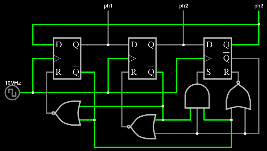
IMO error correction is superfluous.
« Last Edit: 2025-03-09, 14:11:49 by verpies »
   
Group: Moderator
Sr. Member
*****

Posts: 308
Are you sure that the d flip flops will preset and reset at the right time to garuntee proper operation?
   

Group: Professor
Hero Member
*****

Posts: 3666
Are you sure that the d flip flops will preset and reset at the right time to garuntee proper operation?
Yes

Also, despite them being logically equivalent, one method of connecting unused inputs of NOR gates is faster because, in a CMOS circuit, charging two gate input capacitances is slower than one.


Also, didn't you want to generate the clock on-board with additional DS1023 chips ?
   
Group: Moderator
Sr. Member
*****

Posts: 308
Yes

Also, despite them being logically equivalent, one method of connecting unused inputs of NOR gates is faster because, in a CMOS circuit, charging two gate input capacitances is slower than one.


Also, didn't you want to generate the clock on-board with additional DS1023 chips ?

Okay, I reverted to your set/preset version. I think this should work, does it look okay?

The DS1023 has identical pinouts for the different range versions of the chip, so disregard the 50ns version used here.

Edit: hopefully the labels makes the schematic easier to read.
   

Group: Professor
Hero Member
*****

Posts: 3666
Why do you think that the DS1023 chips cannot drive the MOSFET drivers directly and you need the THS3111 as buffers ?
   
Group: Moderator
Sr. Member
*****

Posts: 308
Why do you think that the DS1023 chips cannot drive the MOSFET drivers directly and you need the THS3111 as buffers ?

They'll be driving 50 ohm coax into the driver boards. I'm setting it up so that all of the lines are terminated properly so at high speed it doesn't cause any glitches. The point of separating the boards is so I can tune the coax lengths to account for any delay mismatches in the driver boards. Also to experiment with delayed signals in the future if need be. Trying to make it modular.
   

Group: Professor
Hero Member
*****

Posts: 3666
Which end of the coax cable do you plan to terminate with 50Ω ?
   
Group: Moderator
Sr. Member
*****

Posts: 308
driver side
   

Group: Professor
Hero Member
*****

Posts: 3666
You might find the attached chapter about Intercard Connections informative:
   

Group: Professor
Hero Member
*****

Posts: 3666
Look at the rise and fall times as well as pulse widths, that this guy is able to achieve with modern SiC MOSFETs and freewheeling flyback diode.
https://youtu.be/Od8XmFk3Tm0
   
Pages: 1 2 3 4 5 6 7 8 [9]
« previous next »


Home Help Search Login Register
Theme © PopularFX | Based on PFX Ideas! | Scripts from iScript4u 2025-03-28, 11:43:18
Loading...