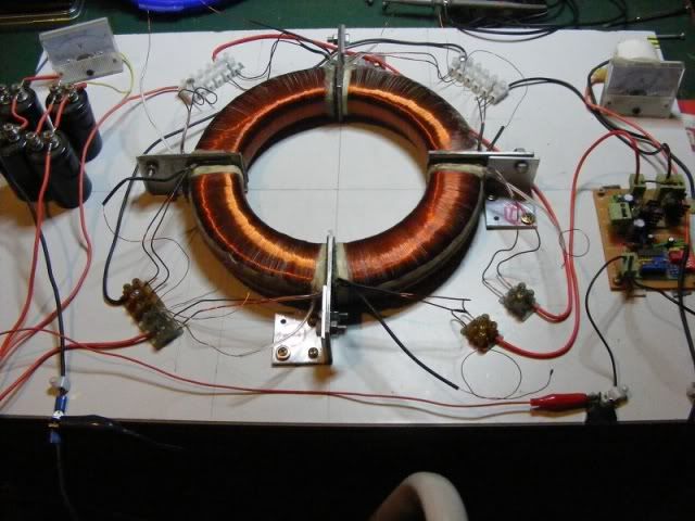
Hi guys, I'm making another converter so I thought I would share.
Here's one I made already, it works quite well, I can get a few different voltages from it.

Tesla Toroid Converters/Transformers.
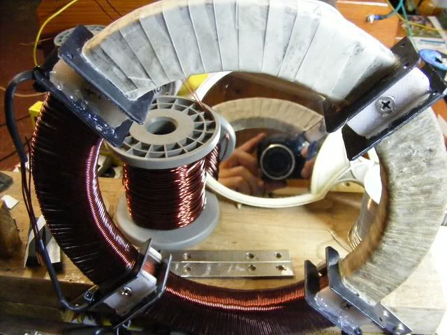
I'm putting a lot more care and thought into the preparation of the core and the mounting,
although it is still very much an amateur construction.
I made the rings for the laminated core from the field of an 8 kW motor, I cut off all the original
pole projections and painted them with red oxide primer. I drilled mounting holes beforehand
I made spacers for between the coils then bound the segments to be wound with coils with a layer of
jute string soaked in melted bee's wax, then I smoothed it over with more wax and wrapped the
segments with a layer of home made bee's wax paper to give a flat surface for the windings.
I'll also use wax and wax paper to make a level surface to wind all the secondary layers on so that
each layer has a nice flat surface to be wound onto.

Tesla Toroid Converters/Transformers.
Each segment will have a primary of 46 turns of two strands of 1mm wire in a single layer
and 5 to 7 secondary layers of 0.5 mm wire. The segments are about 105 mm inside arc at the primary layer.
I'll need to make an appropriate PWM circuit, I'll use a SG3525 PWM chip for the oscillator and probably
parallel some IRF540 or IRFZ48 mosfets for the switches.
I'm hoping that if it is made well enough I might be able to use a rotor with it at least for some experimenting,
with this in mind I'll make it so a rotor can be introduced later. Or I might be able to use it for down conversion instead.
The one I already have can drive MOTs and I use it to power 100 watt Tesla coil as well as run lights and stuff.
It can produce 120v-240v and 480v.
If anyone has any suggestions or idea's I would be glad to hear them.

If anyone has a Silhouette for such a PWM PCB it would save me some work, I'll need to design a circuit then the PCB.
I want it to be able to take lots of current through the switches.
I'm almost ready to start winding secondaries.
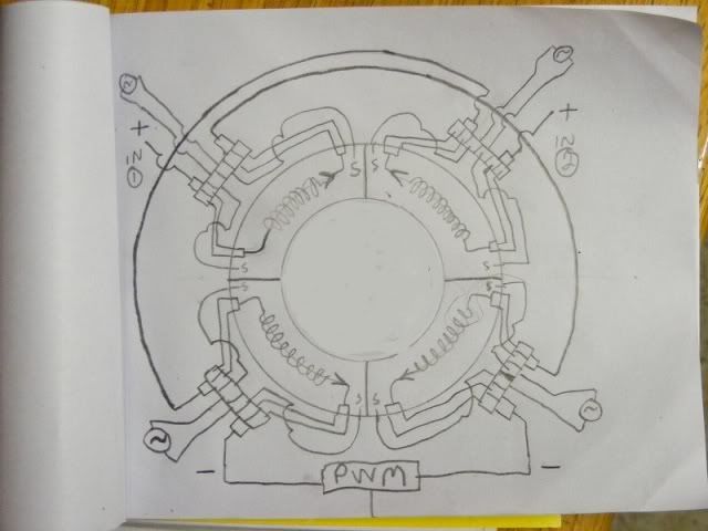
This is an accurate depiction of how I put the primary currents through it, the secondary coils aren't drawn there but the outputs are.
All the coils are wound the same way.

Tesla Toroid Converters/Transformers.
Here's some other info, the reason I call it a Tesla Converter/transformer is I that I go by the scheme outlined by Tesla
in this book Chapter 23 page 109, Also page 17 figure 10 and text and page 42 figure 33 and text there is useful info.
-
http://ia600302.us.archive.org/16/items/inventionsresear00martiala/inventionsresear00martiala.pdfCheers
P.S. The primaries measure 490 uH each with 0.2 ohms resistance.
The secondaries should end up about 230 mH with 1000 turns or so,
that should give me a transformation ratio of about 1:20 or 1:10 depending
on how it is wired up. 1:40 is also possible.
The core weighs 1.8 kgs.
One of the things I intend to try is to build a charging circuit for it by using a variable induction coil
in series with the positive supply line to the coils and a large capacitor for the inductor to discharge into.
..


 Author
Topic: Tesla Toroid Converters/Transformers. (Read 12438 times)